Mousetrap Car
Engineering Exploration Coursework

An engineering exercise where you design a car that's powered by a mousetrap only.
Year
2024

Objective
To design a car that can travel as far as possible by applying the principles of mechanical advantage. The mousetrap car's gear system sacrifices torque (which translate to speed depending on the car's weight) to substantially increase its distance.
Design Description
Overview of Key Elements & Basic Mechanism
The mousetrap car consists of a mousetrap (only power source), a gear system to convert torque to distance, large rear wheels to cover more ground per rotation, and front wheels for balance and less friction on the ground. To minimize weight and therefore optimize usage of the spring’s energy, the car has a barebone design, with only essential, skeletal structures connecting the components.
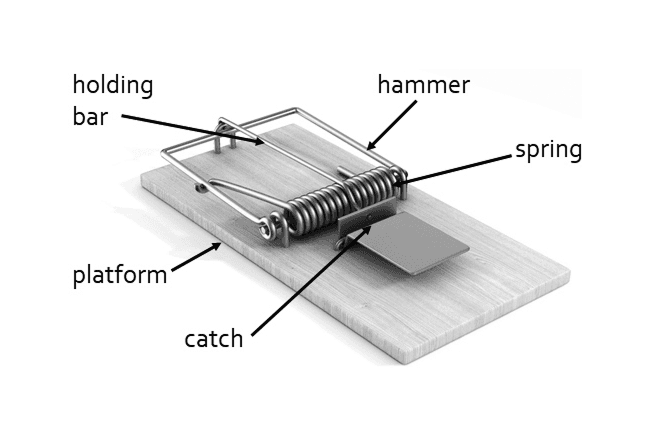
Components of a mechanical mousetrap (Ilin Sergey/Shutterstock).
Fixed to the hammer of the mousetrap is a wooden rod, at the end of which a piece of string is attached. The other end of the string is then wound onto a pulley that drives the gear system, spinning the wheels. To set the car, you pull the trap's hammer back. When released, the spring will pull the hammer back to its original position, pulling the string, which spins the pulley and drives the wheels, accelerating the car forward.
Wheel Size & Design
The two front wheels (d = 40 mm) were designed to be significantly smaller than the rear wheels because their rotation is completely passive, not contributing to any mechanical advantage, so their small size minimizes weight.
The two rear wheels (d = 120 mm) were made much larger because the larger the gear, the greater the distance it can cover with each rotation.
All four wheels are designed to be hollow in the middle: only a middle ring to connect to the driving shaft, an outer ring, and three spokes in between. This minimizes weight and increases rotational inertia (moment of inertia). Compared to uniform, disc-shaped wheels, these wheels will take longer to start moving. However, once they are in motion, their momentum is superior, so the car will coast for much longer once the spring is completely released.
Gear System
The gear system is the most important component of this car. I combined multiple gears placed on two axes. This leads to a very high gear ratio but more points of failure and reduced power efficiency in return: too lose and the gears wobble, but too tight means high friction. To mitigate this, I revised multiple prototypes to find the optimal tolerance and clearance between the gears, reducing backlash and increasing transmission efficiency.
First, the small pulley (d = 15 mm) on which the string is wound is fixed to a large gear (d = 100 mm).
This large gear drives a smaller gear (d = 20 mm), which is fixed to another large gear (d = 100 mm).
Once again, this large gear drives another small gear (d = 20 mm), fixed to an axle and fixed to the wheels (d = 120 mm).
This produces a total gear ratio of 200:1, which means that for every 1 cm of string being unwound by the string, the car will move 200 cm. The gears are designed to be hollow in the middle, for reasons similar to the wheels. All gears are fitted with ball bearings to facilitate smoother rotation, allowing the coaxially placed gears to smoothly spin at their own speeds.
Lever Arm Length
The lever arm measures 5 cm, which provides a more limited mechanical advantage compared to a longer arm. I initially experimented with the latter, but the torque became too low: the car would only move if placed on a perfectly flat surface with no bumps. Therefore, I decided to settle on 5 cm, since the 200:1 gear ratio was already exceeding the goal.
Material Choices
The wheels are made of laser-cut acrylic for high strength and low friction, while the rest of the body was made of lightweight 3D printed PLA to lower the overall weight, with the skeletal structure only having supports where necessary.
Outcome
In our model, the mousetrap car can travel a maximum distance of 26.93 meters in 35.3 seconds. However, in reality, our car traveled only 24 meters, including the coasting distance (movement due to momentum), and the actual time was 37 seconds. According to the model, when the car reached approximately 24 meters, the time was 24.4 seconds, highlighting a discrepancy between the model and real-life results. Additionally, the driving force in the model dropped to zero after the car had covered 20 meters, meaning that for the next 15 meters, the car moved solely due to momentum. In reality, however, the momentum only carried the car about 0.5 meters further.
One possible explanation for this difference is that in reality, when the car moves, it is also affected by wind resistance, which means the car requires more force and time to travel.


